|
(b-2a-1)
|
About 1869 or l870,
William E. Hale of Chicago patented and introduced his "Water-Balance
Elevator," which used a pump along with the power of gravity. At the
top of the hoistway, a large diameter sheave spanned the distance
from the center of the hoistway to the center of a large tube adjacent
to, and extending the length of, the hoistway. The lower end of
the tube terminated in a large underground tank. On the roof, directly
above this tank, was another to which a steam pump drove water.
When water from the upper tank was released into the traveling bucket,
the weight drove it down -- and the elevator car upward. When the
bucket reached the bottom, a valve controlled from within the car
emptied the bucket, thus allowing it to move upward and the car
downward. The car cage was supplied with a powerful spring-loaded
brake which left to itself would set upon steel guide rails -- long,
thin flat bars about a half inch by six inches. The brake was released
with considerable effort by the operator in the car. Stops at intermediate
floors were accomplished by application of the brake. This was the
fastest elevator of its time (capable of 1,800 feet per minute!)
and the lifting capacity was only limited by the weight of the water
and the strength of the materials and design of the components.
It required great skill, strength and caution to operate, however,
and the installation costs were great because of the second shaftway
which, of course, had to be waterproof! The popularity of Hale's
elevator waned after a few years as more rational steam pressure
hydraulic designs became available.
(Graphic Source: Elevators by Jallings) |
|
 |
(b-2b-27.gif)
|
|
As a means of economy, the Armstrong elevator used three small
cylinders on a crosshead, admitting water into one, two or three
on the basis of the loads. However, the mechanism proved too complicated.
John Fensom of Toronto developed a scheme using a pipe connection
at the front and back of the cylinder in such a way that the water,
after being used for hoisting, was discharged on the lowering
trip into the other end of the cylinder. On the next trip up, water
was forced into the overhead tank. The long end of an overhead
lever was weighted to meter the flow of water for heavy loads,
as indicated in previous graphics.
|
|
|
(b-2b-30.gif)
|
|
The end of the long iron lever with the Fensom balancing device
was weighted so a heavy load placed on the car would overbalance
the lever. The lever end would lift a rod to release a valve,
allowing water to flow into the sewer, relieving back pressure
on the piston and allowing more weight to be lifted. Water was
thus saved only when light-to-medium loads were lifted. That saved,
however, was found too foul and oily for other purposes and the
scheme abandoned.
(Graphic Source: Elevators by Jallings)
|
|
|
(b-2a-3)
|
|
Hale's "Standard Hydraulic" was more successful than his try
of four years previous. It used a circulating pipe system that
allowed water, after it had been used above the piston, to be
returned during the succeeding stroke to the underside of the piston. This proved more successful and economized
on the amount of water used. The cylinder and valve are detailed
in the next two graphics.
(Graphic Source: Elevators by Jallings)
|
|
|
(b-2b-31)
|
|
Details of cylinder and valve of Hale's "Standard Hydraulic."
(Graphic Source: Elevators by Jallings)
|
|
(b-2b-32)
|
|
(b-2b-16.jpg)
|
|
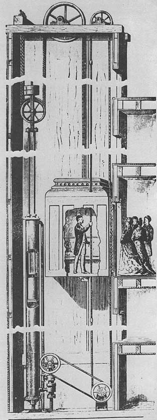
The Water Balance lift of Carl Flohr used a counterweight (accumulator)
upon the piston rods to assist in forcing water back to the tank
on the roof. The ropes to the plunger side were 2:1 so the car
moved two feet for every one foot of piston movement. The next
graphic indicates how the operator in the cabin was able, by means
of the tiller rope, to actuate gearing at the valve assembly,
moving small pistons within the piping to add more water pressure
to lift the elevator, then to lower it.
(Graphic Source: Carl Flohr)
|
|
|
(b-2b-16.gif)
|
|
Cross section of the Flohr valve block shows positioning of the
small pistons which, when moved up or down, changed the flow of
water and direction of car travel.
(Graphic Source: Carl Flohr)
|
|
|
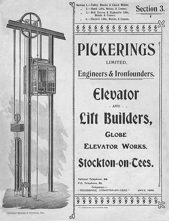
(b-2d-6)
|
| The water balance system
of Pickerings Ltd. at Stockton-on Tees utilized a simple valve block.
An accumulator was affixed to the pistons. Metal ball stops fastened
to the tiller cable automatically shifted the cable and stopped
the car at each terminal. Note metal ratchet, inserted in wood guide
rails, upon which an undercar safety could set. |
|
|
|
| This Otis water-balance
had much in common with the Pickerings, both using two small pistons,
an accumulator and 2:1 roping. |
|
|
|
| In the late 1870s,
Otis Brothers & Company developed a hydraulic beam engine of considerable
merit although less than a dozen were installed. The prime motivation
for its manufacture was to occupy the space and position of the
prevalent steam engine. Balance weights were placed upon the moving
beam. The cylinder was double-acting and the car overbalanced, about
equal power being used in both directions, as became customary later
with electric elevators. The gearing was 10:1 on the sheaves and
2:1 on the beam, total of 20:1. This machine was excellent in all
respects but could not compete with the roped hydraulic types on
the horizon. |
|
|
|
| The horizontal pushing
cylinder was installed in a number of important American buildings,
particularly in Philadelphia. The lifting cable spooled on a drum,
secondary cables running through sheaves, on the same axis, to companion
sheaves. Extension of the piston turned the drum which being of
a larger diameter moved its cable a greater distance. This machine
was inferior to the roped type that became a standard shortly thereafter
for a number of decades. |
|
|
|
|
Rather than accumulator, or metal counterweights, other designers
balanced one car with another as in this Carl Flohr installation
in a Berlin Brewery. Power was through belting from a remote steam
engine.
(Graphic Source: Carl Flohr)
|
|
|
|
|
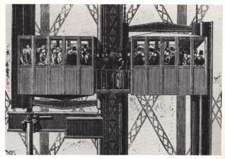
The Otis elevators in the Eiffel Tower counterweighted each other
although the huge steam engines in the basement needed little
help in moving the cars. The reciprocating cars did regulate the
flow of passengers to the upper decks.
(Graphic Source: Der Fahrstuhl)
|
|
|
|
|
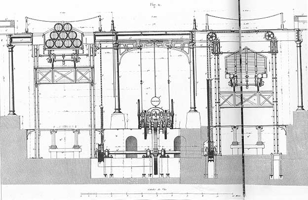
It is difficult to ascertain exactly how the driving force was
utilized by this massive reduction gearing to raise and lower
rail cars between the surface and an underground repair shop.
A hydraulic cylinder is shown along with a steam engine. However,
it is clear that one car balanced the other through sheaving,
common axles and chains. This system was built by Compagnie des
Chemins de Fer P.L.M. at Paris-Bercy Station in 1858.
(Graphic Source: Going Up)
|
|
|
|
|
The first direct hydraulic lift, installed by Edoux in 1887,
was actually counterbalanced. It is not often pointed out that
this design was counterweighted. with chains leading from the
bottom of the cylinder (through sheaves so placed as to provide
traction!) to a heavy metal sleeve sliding upon the inner wall
of the cylinder.
(Graphic Source: Going Up)
|
|
|