|
(c-3a-1)
|
|
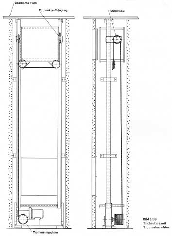
The drum machine was particular adapted
to the short travel lift such as this undercounter underslung
dumbwaiter. The drum could accommodate the small length of wire
rope required and the light capacity of the car might well eliminate
the need for a counterweight and accompanying wire rope to drum.
Graphic source: Der Aufzugbau
|
|
 |
(c-3b-4) |
|
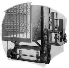
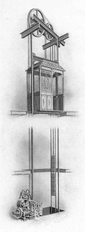
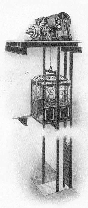
"Because of the usual unsatisfactory
results obtained with hydraulic power, The Kerscher Elevator Co.
has developed the electric cradle lift type elevator. The major
difficulties of the hydraulic elevator, operating from an outside
water supply, is the difficulty of eliminating leakage at the
valves and packing glands, and the freezing of water in the winter.
Should the water contain sand or other abrasive materials, the
valves and packing are soon leaking. This causes the elevator
to "creep" which is dangerous and makes positive control
difficult. Freezing results in an expensive thawing out repair
bill. Where the hydraulic type is operated by a pump, excessive
noises often result. The electric cradle lift type
has been developed to eliminate these disadvantages of the hydraulic
type. These elevators are designed for capacities ranging from
several hundred pounds to 6,000 pounds, and speeds ranging from
20 to 60 feet per minute. The control may be Constant Pressure
or Full Automatic."
Graphic Source: Kerscher Catalog
|
|
|
(c-3a-2)
|
|
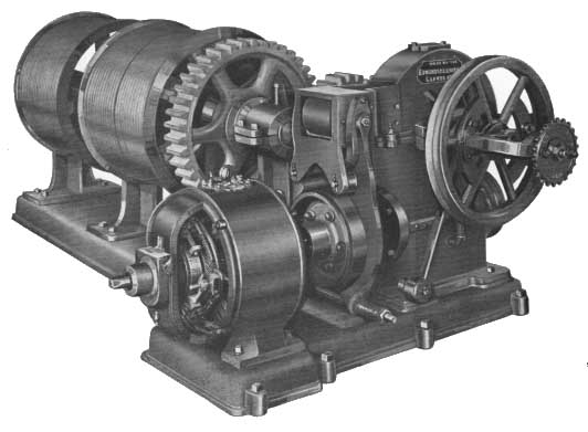
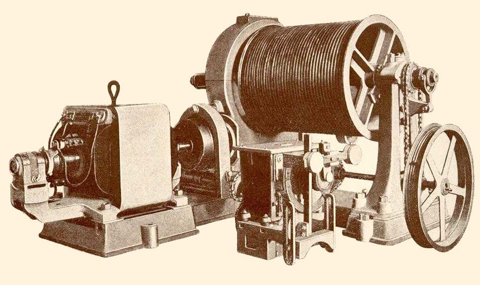
Edmonds Elevator (U.S.), back-gear drive
machine with drum for hoist and counterweight cables.
Graphic Source: Edmonds Elevator Company Catalog
|
|
|
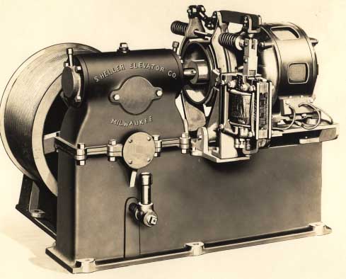
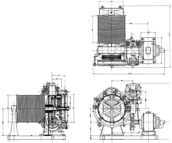
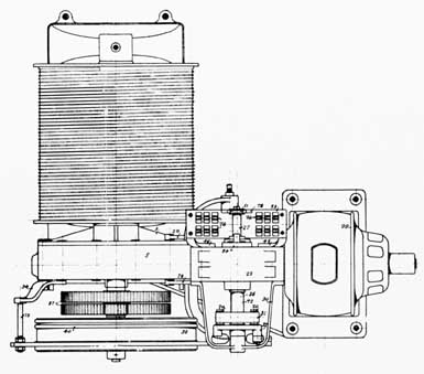
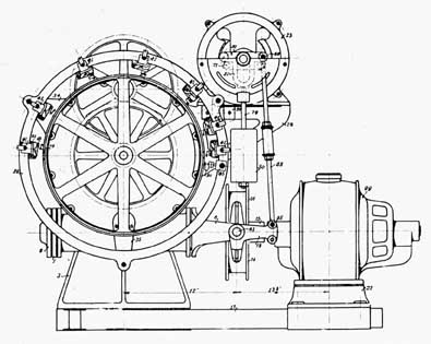
(c-3a-3, c-3a-4)
|
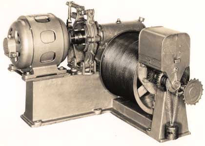
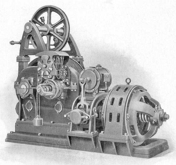
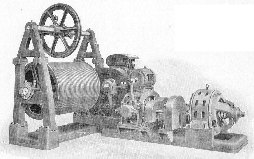
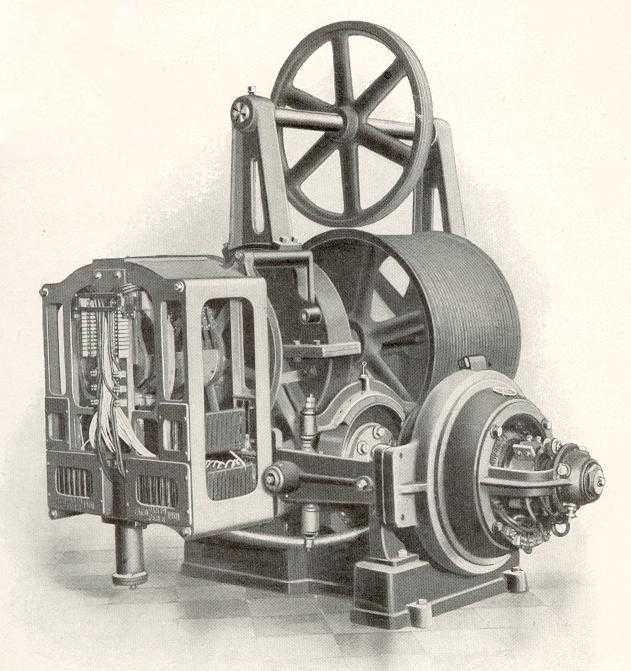
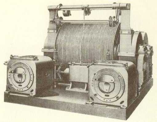
| Front and
rear views of S. Heller direct connected worn over gear electric
drum machine with dash pot brake |
|
|
(c-3a-7)
|
|
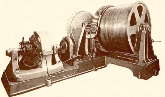
Worm and gear driving drum. Hand rope control
Graphic Source: Carl Flohr
|
|
|
(c-3a-8, C-3a-9)
|
|
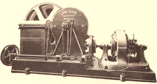
Early spur gear machine drive drum. Notice the bevel gear
Graphic Source: Carl Flohr
|
|
|
(c-3a-10)
|
|
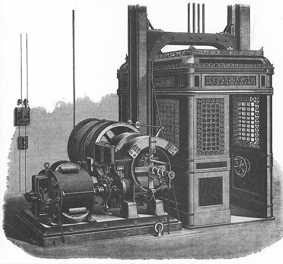
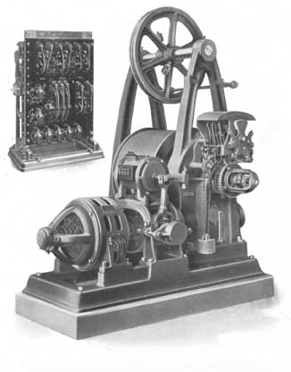
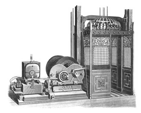
The Morse-Williams elevator displayed at the Chicago exhibition
of 1898 was an example of the electric elevator in its earliest
commercial form, with the motor connected directly to the load.
By this time, incandescent lighting circuits in large cities were
sufficiently extensive to make such installations practical. However,
capacity and speed were limited by weaknesses of the control system
and the necessity of using a drum.
Graphic Source: Going Up
|
|
|
(c-3a-11)
|
|
Otis Drum Machine with varying rating. The No. 4 D.S. machine
is arranged to take three different size motors as mentioned in
the duty tables, viz: No. 15, 20-A and No. 20. The duties range
from 45 feet to 80 feet speed and loads of 5,500 lbs. to 10,000
lbs. for the internal gear machine. For the straight machine,
the duties range form 4,500 lbs. at 100-ft. speed to 2,000 lb.
at 250 ft. speed with the no. 15 motor. The machine with no. 20
motor has duties ranging from 5,000 lbs. at 150-ft. speed to 3,000
lbs. at 250 ft. speed.
Graphic Source: Otis Indicator November 1911
|
|
|
( c-3a-13)
|
|
With the No. 4 D.S.A.C. Machines an arrangement of back gears
can be provided for use when heavy safes are to be hoisted in
office buildings. These gears are made for two ratios of speed
reduction, 4:1, for use when the car speed with ordinary loading
does not exceed 200 feet per minute, and 9:1, for speeds above
200 ft. per minute. The back gears are mounted on a shaft which
runs in sliding boxes supported on stands bolted to the bed plate
on the side of the machine next to the drum. A pinion on the rotor
shaft drives the first back gear and a pinion on the back gear
shaft drives a gear on the worm shaft. When these back gears are
not required, the shaft and boxes are moved to the extreme outward
position, disengaging the gears. The boxes are held rigidly in
position by pins. When a safe is to be lifted, the sleeve coupling
between the rotor shaft and worm shaft is removed and the back
gears moved up into mesh.
Graphic Source: Otis Indicator December 1911
|
|
|
(c-3a-17, c-3a-18)
|
|
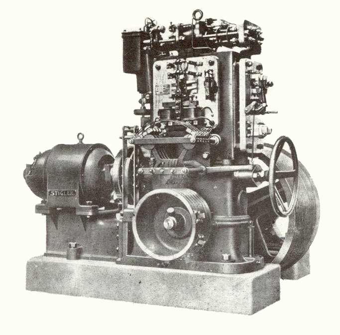
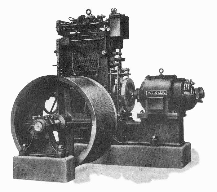
Two views of Stigler drum machine. Note wheel for lowering in
event of power failure.
Graphic Source: Raffronto fra le norme vigenti sugli
|
|
|
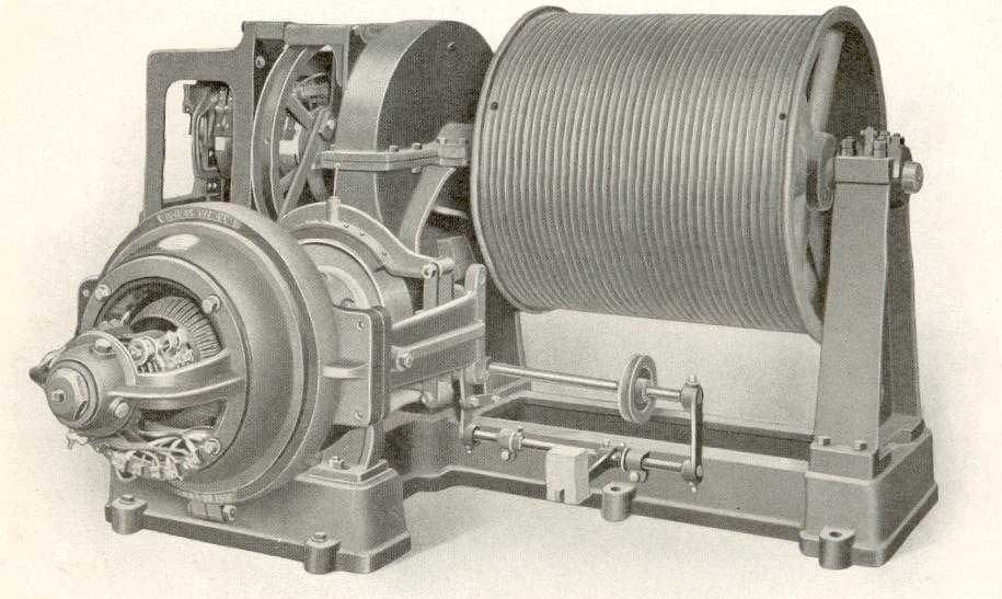
(c-3a-19, c-3a-20, c-3a-21, c-3a-22)
|
|
Without too much change in reduction gearing and control equipment
was adaptable to overhead or floor installation. Note termination
holes in near each rim of the drum. While hoist cables wound from
the center outward the counterweight cables were winding inward
in the other direction. Pressure on the drum and bearings was
maintained as evenly as possible. Grooves in the drum assured
that cables wond on and off smoothly and orderly.
Graphic Source: Eaton and Prince
|
|
|
(c-3a-23)
|
|
The 'Micro-Drive', a self-leveling system for elevators devised
by Otis and generally accepted as another fundamental advance
in sophisticated elevator technology.
Graphic Source: Going Up
|
|
|
(c-3a-24)
|
|
Otis automatic residence drum machines 1912 were used in huge
mansions and thus little different from machines used in commercial
establishments.
Graphic Source: Otis Indicator January 1912
|
|
|
(c-3a-27)
|
|
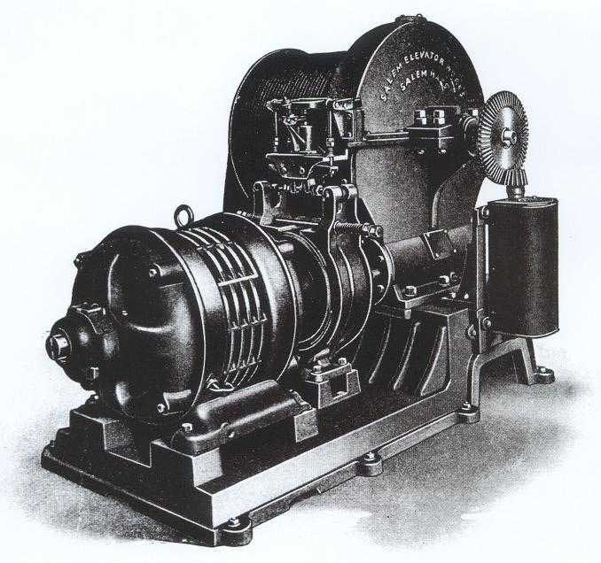
"This is our latest Direct Coupled Electric Drum elevator
machine, built for capacities up to 10,000 lbs., and for both
direct and alternating current. It can be used for either freight
or passenger work, according to the size of drum and gearing;
for car speeds from 45 to 100 ft. per minute for freight work,
and for passenger service up to 300 ft. per minute. As with our
traction type elevator, it can be used with hand cable, car switch
or full automatic push-button control. Owing to the few moving
parts, and the simple and efficient safety attachments, it makes
a very satisfactory elevator, quiet in operation, and very powerful.
In general it is similar to our Traction machine, being equipped
with our new electric brake, oil-tight worm gear housing, ball
thrust bearings, etc. It is also provided with our improved electric
machine terminal switch which does away with all moving levers
and small castings, so there is nothing to constantly break as
is the case with many machines using a mechanical terminal stop.
The machine is equipped with an electric slack cable safety device,
which has also enabled doing away with a number of light castings
which are easily broken."
Graphic Source: Salem Elevator Works of Salem, Massachusetts,
founded in 1862.
|
|
|
(c-3a-28)
|
|
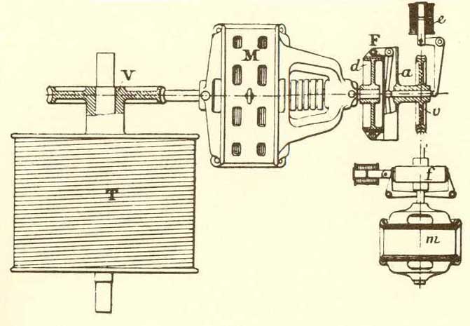
Schematic of Direct-Drive Drum Electric push-button elevator
engine manufactured by The Winslow Elevator & Machine Co., Chicago,
Illinois in 1903.
|
|
|
(c-3a-29)
|
|
Early Otis double worm geared and spur geared drum Electric.
Graphic Source: Der Fahrstuhl
|
|
|
(c-3a-30, c-3a-31)
|
| Two views of drum machine schematic. |
|
|
(c-3a-32)
|
|
London was the first city to develop an underground railway,
the Baker street station being opened in May 1863. The New York
subway was started in 1868, followed by similar systems in Chicago
(1892), Budapest (1896) and Glasgow (1897). By the early 1970s,
35 cities across the world had an underground transport system,
with New York carrying the greatest volume of passengers. London's
Central Line was opened in 1890. Because of its exceptional depth
below the surface - an average of 30 meters - elevators were installed
at each station. After the scrutiny of a variety of proposals,
the construction company opted for a revolutionary system, the
first to be powered by electricity. Forty-eight elevators were
ordered from the Sprague Elevator Company of Watessing, New Jersey.
These elevators were capable of carrying 100 passengers at a speed
of one meter per second, using barely half the energy required
by a hydraulic elevator of comparable power. So successful was
Sprague's elevator that within four years hydraulic elevators
were abandoned, the last being the giant elevator at Shepherd's
Bush station installed in 1904. In the following year Sprague
joined with Otis to cope with the scale of his commitments; 170
elevators for the new London tube lines, Bakerloo, Northern and
Piccadilly in 1906. The majority of these elevators remained in
service for 47 years.
Graphic Source: Going Up
|
|
|
(c-3b-38)
|
|
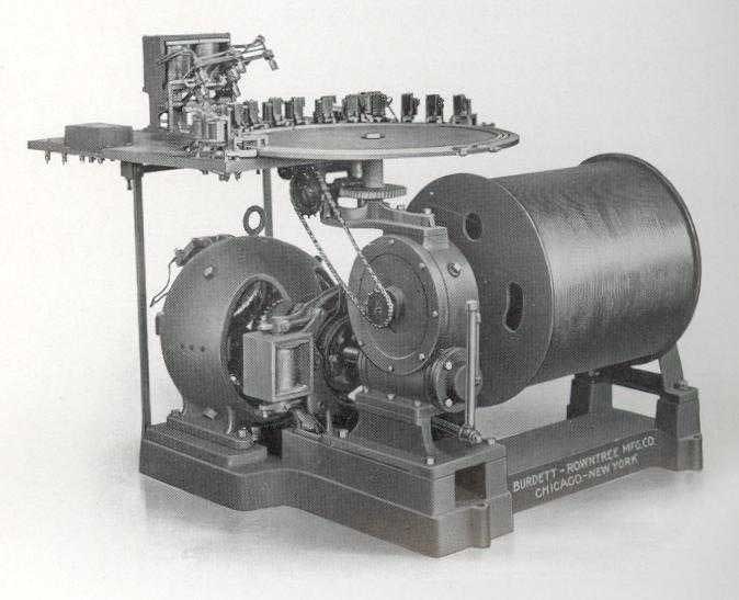
In the early 1900's a dumbwaiter specialists Burdett Rowntree
manufacturing Co. of Chicago and New york City installed this
electric dumbwaiter machine for duties from 100 lbs. at 500 fpm
to 500 lbs. at 200 fpm with a variety of automatic controls for
banks, office buildings, hospitals and government buildings. Fig.
2 shows a central distributing station.
Graphic Source: Electric Dumbwaiter Service
|
|
 |