The Elevator Industry
Human Interest / Elevator Companies Contributing to Technological / Commentary by Industry Veterans / Photos of Industry Veteran Groups in their Environment / Mergers and Acquisitions
Commentary by Industry Veterans
|
The loss of all these buildings probably made Chicago's building program of the next two decades the greatest in American history. The architects and owners had learned their lessons and instituted new features and methods that gave Chicago a position of leadership in the construction industry, which it did not relinquish for many years. It was the birthplace of modern skeleton construction, a term applying to buildings in which external and internal loads are transmitted to the foundation by a framework of metal or reinforced concrete, either separately or in combination. The Tacoma Building, erected in 1890, was the first riveted steel building, although I believe now the Home Insurance Building, finished in 1885 with bolted construction, is acknowledged to be the first skeleton skyscraper. Incidentally, the young firm of George A. Fuller built the Tacoma on a negotiated basis, as there was no way to accurately estimate what the cost would be with this untried technology. It was said that by 1895 there were more steel skeleton type buildings in Chicago than in all the other cities in the country put together. The 21-story Masonic Temple which was built in 1895 was the nation's tallest building and was not equaled in height until 1905, when the Majestic went up. It was not surpassed until 1909 when the 22-story Blackstone and LaSalle hotels were erected. It was 1914 before the 60-story Woolworth Building took the record to New York City where it stayed. However, for 22 years, other cities had to look to Chicago for the tallest buildings. Although it was 1964 before Chicago had its first steam elevator in the Charles B. Farwell store, several years after this type appeared in New York City, the first practical elevator can be said to have been installed in Chicago. In 1870, C.W. Baldwin invented and installed the first hydraulic elevator in a store for Burley and Co. on Lake Street. One of the first Otis patent steam passenger elevators was installed in the Honore Building, but was burned out one year later. J.W. Reedy put an elevator in the six-story Lord & Smith Building in 1872, and Davis steam-hoisting elevators were installed in the Henderson Building in the same year. All this, of course, was before my time, but I do recall that the 12-story Merchants Loan Building had the Fraser elevators with their very elaborate roping arrangement. These elevators ran until 1933 after 33 years of service. Another unusual device was the Cruickshank Safety which operated against a column of wire ropes instead of the guide rails for Marshall Field & Co. for about 25 years, beginning abut 45 years ago. The entire parking system for the Pure Oil Building Garage was designed and built by the Wheeler Elevator Co. The motors were supplied by the Imperial Electric Co. and the controllers and accessories by the C.J. Anderson Co. The fire doors and guides were furnished by St. Louis Fire Door Co., according to Wheeler specifications, but the operating mechanism was designed and manufactured by Wheeler. After the garage project, Gallaher and Speck bought Wheeler, and C.W. Wheeler became associated with the new company as chief engineer. He was a very ingenious man and designed many unusual applications outside the elevator field, including exterior prison doors, doors weighing many tons for arsenals, the Argonne National Laboratory and special bridge-lifting equipment. As I mentioned, Chicago was a pioneer in many respects. Back in 1920 when the Chicago Tribune offered US $100,000 in prizes for an architectural plan, Finland's Saarinen submitted a new concept of tall office building design that was to set a pattern for all future office buildings in its completely functional and vertical design. It did away with cornices, belt course and imitation of classic architecture. He had a great influence on architecture, just as Chicago had a great influence on all other cities of the nation. |
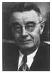
 RAY
BERRY, PRESIDENT, GALLAHER & SPECK
RAY
BERRY, PRESIDENT, GALLAHER & SPECK |
The helper carried a regular machine shop for the mechanic in a big leather bag with a strap, and those tools went home every night; all 50 pounds of them. There were no dainty tools as we have today; everything was heavy, and the main asset of the helper was enough muscle to carry that tremendous bag. He had to know how to do one other thing, when he got on the job, secure a box for the mechanic to sit on. A good helper made US $8.00 a week; an average mechanic made US $12.00 and a top mechanic made US $18.00. I got into the door business with the Quincy Elevator Gate Co. in the late 1920s. Of course, wooden gates were popular then and it was before the counterbalanced door gained wide acceptance. We made a vertical collapsing gate that was operated by a penthouse machine. Later I managed the Door-Motive Co. of Detroit until Peelle bought it out. Master door-operating units in the penthouse were popular until the individual motor-driven sheaves were invented. As sales manager and later vice-president for Peelle, I had contact with elevator companies all over the country, and two of the most important things I saw happen in our industry were the emphasis on maintenance and the ability of the elevator companies to sell directly to the customer. It's strange that in the past few years there should be such a great stress on the part of subcontractors to get out from under the general contractors. The elevator companies, led by Otis, recognized the value of this many years ago. Our industry was a pioneer in this concept. You also hear an emphasis now on the evils of bid-peddling as if this were something just invented. You couldn't even trust some of the public stenographers in the old days; you'd borrow her typewriter, instead, to fill in your bid. A sealed bid was no security at some of those openings. It got so bad that the architect or owner would pass down the aisle with a basket, and each bidder would throw in his envelope a few seconds before opening time. The salesmen of those days had to be hard entertainers, and the strain broke some good men. Now a salesman has to be a good technical man instead of being able to hold his liquor. Speaking of technical men, the old time mechanic was a far better mechanical man than his counterpart today. He practically had to build an elevator in the field and many of the men were fine machinists as well. Now the technicians are in the factories, and the equipment comes out in more of a package. Of course, the present-day elevator constructor is in another world from the old-timer, electrically. |
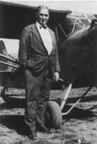
 FRANK
BUCKRIDGE: THE PEELLE CO., RETIRED
FRANK
BUCKRIDGE: THE PEELLE CO., RETIRED|
Mr. Peter B. White, an engineer of the city of Chicago, realized the usefulness of this patent or device more for safety purposes than for fire and enlisted the cooperation of the W.H. Chenoweth Co. who were then the pioneer ornamental and steel door manufacturers in Chicago. This company introduced the Meaker door for the purpose of safety devices rather than fire.
The W.H. Chenoweth Co. continued to manufacture these doors solely until the patents expired. I associated myself with the W.H. Chenoweth Co. in 1890. Then, on the first of January, 1893, became one of the managers of the Variety Manufacturing Co. When the Chicago Auditorium Building was built in 1888, a number of Meaker doors were erected in this building. They were made of a 1 x 1 x 1/4" angle, of No. 24 gauge corrugated steel. Light Morton chain was used running over No. 4 Moore sheaves. Up to this date, these doors are giving perfect satisfaction. I could name dozens of buildings in which these doors were erected and are still in working order in 1927.
As necessity is the mother of invention, Mr. W.A. Cross, one of the engineers of the Variety Manufacturing Co., designed a door which would take up much less space in the shaft and required only 10'10" from floor to floor for a 7' clear opening. (I show herewith a small cut [Figure 2] illustrating how this was accomplished.) Patents were issued for this door which was known as the Cross Improved Elevator Door on May 19, 1896, and of the thousands that were erected by the Variety Manufacturing Co. in Chicago, the requests for repairs have been practically nil. In the days of the old Meaker door there was no such thing as a testing laboratory for the insurance companies, so that this particular door was never put to a laboratory test. On October 27, 1903,
a fire test was made at the Chicago Underwriters' Laboratories (then
in an alley on 21st Street) of the Cross Improved The requirements of the National Board of Underwriters were becoming more and more exacting, and the manufacturers had to keep pace with their demands, so gradually the heavy constructions of doors came into use. The latest design in heavy-duty construction was installed in several buildings of the Sears Roebuck Co. This corrugated iron door is seen in Figure 3. |
 W.B.
GERVAIS: HISTORY OF THE COUNTER-BALANCED DOOR
W.B.
GERVAIS: HISTORY OF THE COUNTER-BALANCED DOOR 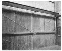 (I
herewith show a small illustration [Figure 1] of how this particular
door was made and call attention to the fact that doors erected
in one plane, a 7' opening required a 14'6" floor height.)
(I
herewith show a small illustration [Figure 1] of how this particular
door was made and call attention to the fact that doors erected
in one plane, a 7' opening required a 14'6" floor height.)  In
the latter part of 1895, we were asked to erect doors in the Young
Women's Christian Association on Michigan Boulevard, then known
as Michigan Avenue. These floor heights were exceedingly low and
not enough space existed between the elevator shaft and the floor
to put in staggered guide doors.
In
the latter part of 1895, we were asked to erect doors in the Young
Women's Christian Association on Michigan Boulevard, then known
as Michigan Avenue. These floor heights were exceedingly low and
not enough space existed between the elevator shaft and the floor
to put in staggered guide doors.  Elevator
Door, and needless to say, it was found wanting in a great many
respects, as the light construction had been inherited by us and
was still followed.
Elevator
Door, and needless to say, it was found wanting in a great many
respects, as the light construction had been inherited by us and
was still followed. |
We have never yet heard of one requiring re-boring, and are sure we never shall, as they will last a lifetime with ordinary good care. All the other parts of the machine will wear out before the cylinder will need re-boring. We always guarantee our piston packing to last one year without replenishing. We have had many of them run two years and some three years, constantly, without re-packing, depending upon the care they receive. The work of adjusting the packing and replacing when worn out can be done from the open end of the cylinder, by an ordinary mechanic, or janitor of the building, and will not cost over 10% of the same service with any vertical machine using rubber and leather packing. We will tell you why: Our cylinder, being open on the end, admits of being lubricated with a mixture of plumbago and lard oil, which reduces the friction and wear of the parts to comparatively nothing. A glazing of the plumbago is formed in the cylinder on which the soft packing travels and seems never to wear or touch the iron; and with our new method of oiling, it is very easily applied and keeps everything clean. This oiling is impossible with vertical cylinders taking water at the top. Again, our pistons travel very slow - an average of one-tenth the speed of the car, or six feet for a car travel of sixty. In most vertical machines, the piston travels one-half the speed of the car, or five times faster than ours. Parties using the vertical cylinder will invariably use the horizontal pump, making over one hundred times more piston strokes to pump the same water, which rather damages their argument. We also know that nine-tenths of our finest steam engines are horizontals, with the same objections against them. |
 L.S.
GRAVES: HORIZONTAL VS. VERTICAL CYLINDERS PISTON PACKING
L.S.
GRAVES: HORIZONTAL VS. VERTICAL CYLINDERS PISTON PACKING|
JOHN JALLINGS: THE
FIRST WATER HYDRAULIC ELEVATORS The arrangement of the sheaves and cables on any one of these elevators, whether it be vertical or horizontal, is identical with the arrangement of the sheaves and rope in a tackle used in hoisting heavy loads by hand, except as to the point of application of the power and of the load. When pulley blocks and a rope move a heavy load by hand the power available is limited - in fact, the object of the machine is to allow a small power of the tackle, which is so arranged that a mechanical advantage is obtained. If four frictionless sheaves are used, a man can lift a weight four times as great as the force he exerts. However, the weight will be lifted through only one-fourth of the distance through which the free end of the rope is moved. In practice this is not strictly true, for friction has to be subtracted from the theoretical weight which it is possible for the system to lift. With the hydraulic elevator, the conditions are reversed. In this case, there is an abundance of power. By applying this power directly to the sheave and attaching the load to be lifted to the free end of the tackle, the large amount of power is so distributed as to lift a smaller load through a correspondingly greater distance. When water under pressure is admitted to the cylinder, it forces the piston along its bore and, through the medium of the piston rod to which it is attached and the crosshead, it pulls the set of movable sheaves away from the set of fixed sheaves. The hoisting cable is attached at one end to the frame which holds the fixed sheaves and is wound around one of the sheave in the crosshead. It is then passed underneath to one of the fixed sheaves, then around, over, and back to the second sheave in the crosshead with the process being continued with all the sheaves. The cable is finally carried up to the hatchway to the sheave at the top of the run, over it, and down to the car. When the piston moves, the car moves a proportionately greater distance, depending upon the number of sheaves that are used. |
|
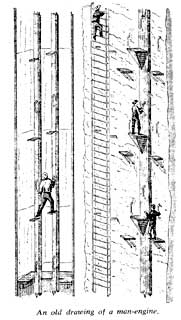
C. MCCOMBE: AN ENGINE
TO KILL MEN So bad were the conditions that the exhaustion of miners working in the Cornish Consolidated Mines prevented the older and more experienced men reaching the deep levels. They were exclusively operated by the younger and inexperienced. Small wonder that deep mines were unpopular and such ventures had their labor problems, even in the early nineteenth century. However, an ingenious solution was at hand. Far off in the Hartz Mountains, Bergmaster Dorrell of Clausthal was supervising the driving of great wrought-iron nails into the pairs of wooden pump rods which plunged downward to the bottom of one of the local mines. These substantial baulks of timber reciprocated backward and forward within a foot or two of each other. Using the Bergmaster's invention called for a cool head. All the miner had to do was to spring on the topmost peg at the summit of either rod's stroke. As the rod lunged downward, to pause for a split second before the return stroke, the miner had the chance of transferring his position to another peg which was driven into the opposite timber pump-rod, then at the top of its stroke. By repetition of this hair-raising procedure, the miner could descend the mine at an unheard of rate. Depending on one's point of view, the return journey was just as easy - or hazardous.
Further development proceeded apace. The primitive wrought-iron pegs were replaced by comparatively roomy platforms with a grab bar fixed at chest height. Shafts were also designed to incorporate this new system which quickly became known in Britain as the "man-engine." The technique was not dependent upon the use of two reciprocating rods; a single rod could be used in conjunction with a single or double flight of sollars attached to the wall of the shaft. This method, although slightly safer, was only half as fast as the technique employing double rods. Nevertheless, where capacious sollars and two flights of side platforms were used, a shift of descending miners had no difficulty in passing an ascending band of workers en route for the surface. Although the single-rod version of the man-engine eventually came into universal use in Britain, further development work, carried out abroad, produced four-rod versions. Other experiments using wire ropes were concerned with lessening the weight of the great lengths of timber which together made up the reciprocating rod. The shafts which held the man-engines were often far from vertical with several changes of angle during their descent. In such cases it was necessary to accommodate the change in angle by guiding the jointed reciprocating rod over rollers. It was in 1834 that the Royal Cornwall Polytechnic Society offered a prize for the best model of a machine for lifting miners to the surface from deep mines. The premium was awarded to Michael Loam for a model of a man-engine similar to the German pattern. Loam had been interested in man-engines for some years, having previously read a paper to the Devon and Cornwall Miners Association on the history and development of the man-engine concept. The model submitted by Loam had an interesting feature insomuch that he incorporated a triangular cam revolving in a rectangular frame. When one of the three points of the cam came into contact with the frame, it caused a momentary pause in the movement of the reciprocating rod. This was intended to correspond to the fleeting alignment of the pump-rod platforms with the sollars, so that the miners could step on and off in safety. At other times in the rotation of the cam, movement was accelerated. Despite the interest generated by Loam's model and the offer by the Polytechnic Society of a subsidy for such a system installed in a Cornish mine, it was not until 1842 that the mine adventurers at Tresvean decided to take up the challenge. The Polytechnic had offered £300 for the first 182 meters and £200 for the subsequent 182 meters dependent upon a successful operating period of two months. By the beginning of 1842, the experimental engine had reached 43.7 meters. Its initial success persuaded the adventurers to carry the work down to the 1,680 feet (510 meters) level at an expense of £1,670. The trial section was based upon two parallel rods actuated by a waterwheel. The stroke was 12 feet (3.66 meters) at a rate of five strokes per minute, thus providing a rise or descent of 60 feet (18.3 meters) per minute. The waterwheel was presumably replaced by a steam engine, as a later source refers to a double rotary 36-in (0.91-m) cylinder engine acting on two small wheels which acted in turn on two larger wheels. Not all the miners looked at these developments with unalloyed enthusiasm. Many older men, apprehensive about the agility and nerve required to use such a fearsome contraption, would have nothing to do with the idea and declared the mine owners were erecting an engine to kill men. Brushing aside the objections, the mine authorities arranged for pupils from the local school to travel down to the 18- m level, the return being equally free from accident - a typical nineteenth century solution to a ticklish development problem! Despite the conservative attitude of some miners, the success of the Tresavean engine was praised by a local bard known as the Gwennap Poet who wrote: "The engine by which he is raised from below, Now supersedes climbing, health's deadliest foe - "This miners know well and their gratitude show, Their core being O'er, from labor they cease, And delighted avail, O Loam, of the ease, Thy genius procured them and joyful ride, On the rod, while others descend by their side." Three years later a second man-engine was installed at the United Mines. This was to be the last of the double rod versions. Henceforth all Cornish man-engines were of the slower, marginally safer single-rod type. Sixteen engines were built over the next 50 years or so in Cornwall while in Europe, 30 engines were in use by 1865. The man-engine at Devon Great Consuls occupied a shaft with a depth of 1,020 feet (311 meters) with landings at intervals of 12 feet. These sollars were pierced by openings through which the 8-in. square timber rod reciprocated. The platforms on the rod were 18 by 15 inches (0.46 meters by 0.38 meters) and the openings in the sollars 27 by 24 inches (0.68 meters by 0.61 meters). A typical European man-engine was that at the Maria Shaft at Przibram in Bohemia. The engine reached a depth of 3,000 feet (912 meters), the rods being forged from the best steel. The square section was one inch by one inch (2.54 cm by 2.54 cm) at the bottom increasing to 3-1/2 inches by 3-1/2 inches (9 cm by 9 cm) at the surface. The rod sections were connected at intervals by means of dovetails. The sollars were fabricated from sheet iron with a thickness of 1/7 inch (4 mm) and of an area sufficient to accommodate two men. The total weigh of the reciprocating load was 77 tons, a figure which increased to 95 tons when 260 men were riding to the surface. The engine is reported as having a 22-inch diameter (0.56 meters) cylinder and a 3-ft 8- in. (1.12-m) stroke. Safety of such structures was a problem, the engines being far from accident free. Every 100 meters or so catch pieces flanked the reciprocating rod. These were designed to prevent the rod failing much more than the normal stroke in the event of a failure. This system of a single rod provided the means of almost closing the shaft with the equally spaced sollar platforms through which the rod reciprocated. Sloping boards under each sollar guided the miners' heads towards the rectangular hatch in each sollar. The double rods, working in an almost open shaft, were more prone to accidents. In 1880, 11 men died in the Abraham mine in Freiberg due to a rotten pump rod. A tragedy involving another 11 miners occurred in the Rosenhof shaft at Clausthal about the same time. Figures are available for the seven years, 1873 to 1879, for the annual death rates for miners using man-engines in Cornwall. They were 0.14 per 1,000 persons riding such systems, enough to send a present-day factory inspector into a decline. Yet, it was claimed that the system was far safer than ladders whose toll for the same period was quoted as 0.21 deaths per 1,000 men. Simonin in a book entitled "British Mining," published in 1884, makes no bones about the hazards involved in riding a busy engine. "There must be no hesitation. If the place should happen to be already occupied on the ladder, or on the stage fixed against the shaft, by one miner who is going up as another is going down, he should remain quiet in his place and wait for a second movement. The slightest embarrassment may cause the most serious accident and the brutal engine, by its sudden return, may kill the traveler on the spot or break a limb." The safety of such a system was not improved by the habit of some miners who chose to travel up and down the rods without lights despite the fact the sollars were often slippery with mud and grease. In spite of the risks inherent in the system there was the great advantage that the miners could step on and off at any level they chose. Improvements in other devices for raising men from the depths of mines were developed in the latter part of the nineteenth century. They were like the man-engines in earlier years, regarded with fear and suspicion by the miners in the West Country. "A Cornishman does not like to hang to a rope" was the reaction of many men to the newfangled winding gear. Nevertheless, change was on the way; only the Cornish Levant Mine, clinging to its cliff-top eyrie above the sea still retained its man-engine as late as the first World War. The end was brutal and sudden. "Cornish Tin Mine Disaster," "Failure of a Man-engine" screamed the headlines on a mid-October day in 1919. The engine built to kill men had finally lived up to its name. At three in the afternoon, the ponderous wooden beam had parted at the nose of the connecting rod when the steam engine was nearly at the top of its stroke. At that precise moment some 150 men were en route for the surface. Failing free the beam crashed and re-bounded from the walls of the shaft carrying with it the safety stops. Only at the 300-m level did the safety devices hold. Many men were dashed from their stances and crushed against the sides of the shaft, smashing away other sollars and platforms as they fell. Rescue parties were quickly on the scene, but the task of extracting the dead and injured was extremely difficult. By the following night, only nine bodies had been recovered, another miner dying after reaching the surface, leaving 21 men unaccounted for. The final death toll stood at 31. At the inquest, it was revealed that the wrought-iron strap connecting the man-engine rod to the nose of the engine beam had fractured due to an undetected flaw in the metal. The disaster spelt the end of this form of vertical transport, already obsolete, having been long overtaken by other forms of haulage and winding gear. |
 The
Bergmaster introduced his idea in 1833, the initial experiment enabling
miners to reach a depth of about 200 meters. The success of this
method of transporting miners to and from their work was reflected
in its subsequent adoption in many European countries. Bergmaster
Dorrell installed another system, again based on two reciprocating
pump rods driven by a waterwheel, in 1835, reaching a depth of about
420 meters.
The
Bergmaster introduced his idea in 1833, the initial experiment enabling
miners to reach a depth of about 200 meters. The success of this
method of transporting miners to and from their work was reflected
in its subsequent adoption in many European countries. Bergmaster
Dorrell installed another system, again based on two reciprocating
pump rods driven by a waterwheel, in 1835, reaching a depth of about
420 meters. |
California adopted a code in 1916, and Ohio placed its in effect in 1924. The Ohio code, like that of New York City, was very brief and covered general requirements only. The New York City document restricted speeds to 700 feet per minute and this had to be revised to permit the installation of 1,000 feet per minute cars in the Empire State Building in 1931. After 41 years, I left Otis in 1950 and devoted all my time to code work. I suppose the U.S. has taken the lead in this field, as we have had requests for information from all over the world regarding our work; from Holland, Germany, Sweden and other distant places. We have testified through the years in many escalator accident cases; probably 40 or so since 1950. I don't think the accidents are caused by the speed of the stairs but by where people step. You know, the old escalators installed in the London "underground" back, I believe, in 1904, traveled at a speed of 190 feet per minute, about twice as fast as the modern average. You've probably seen some of the old stairs in Macy's (there are over 70 units there, the largest installation in the world) that have wooden balustrades and cleats on the steps. There is 3/4" clearance between cleats, but they had fewer accidents than on the modern units where the clearance was brought down to 1/8". This is because Macy's catered to a high-class clientele who didn't bring their children to shop, or at least watched them when they did. In some of the kinds of stores using escalators today, the whole family tags along and the first thing the mother says is, "Run along and play on the escalator." She doesn't know where the children are until an hour later, someone finds one and gives her the news that junior is missing part of his sneaker or the seat of his pants from sitting on the treads. The aforementioned Empire State Building was called the "Eighth Wonder of the World," and it was said to have contained more office space than all the buildings in St. Louis or Baltimore at the time. Four old elevators were salvaged from the old building on the site and used to haul the 3,000-4,000 workmen to the upper floors. To save time, rolling kitchens took food up to the men. Although this is not ancient history, it was probably the most dramatic installation in New York City's history. |
 GEORGE
REPPERT: CODE ENGINEER
GEORGE
REPPERT: CODE ENGINEER |
New York City in the 1920s was a busy place. Many skyscrapers were going up including the Empire State Building. These were jobs for Otis, A.B. See and Gurney. Our company got no closer to a gearless machine than Coolidge did to a smile. New York City in the 1920s and 1930s was a city of thousands of basement drum machines, of hand ropes, shipper wheels, knives and clips, monstrous motors and mechanical brakes. Fifty-mile hikes? You didn't need a physical fitness program in those days when you could juggle a Westinghouse C motor, a mammoth that gave out a big 7-1/2 horsepower at 900 rpms; or in the DC areas with Federals and Nationals - large oblong masses of iron, each heavy enough to be ballast for the "Levithan." In 1922, the Edison Co. decided to change the city from 2 phase to 3 phase and from DC to AC. All of a sudden there was a big changeover activity. We bought switches from Payne, mounted them on 1" black slate and wired them up. My father liked the Ryan brake, and we ordered them from Cincinnati. We used the Westinghouse CS motor, large by today's standards, but half the size of what we were replacing. I recall the machine limits and hatch limits came from Payne too; they had fine equipment. Utilizing used material didn't have the stigma attached to it in the old days that it has now. It always involved the fun of a search. Centre Street, in lower Manhattan, was the street of second-hand motor shops at that time. Police headquarters was there and still is. Flanagan's was on Centre Street, a restaurant that served the best roast beef and beer in New York City. We toured the motor shops and probably ended up with something like a G.E. type K.E. for about US $25. Then we'd go up to East 5th Street and the Bowery, which was in its prime as a "bum-haven," and they'd roll out in the middle of the street. We'd pick up a good board for US $5. If you stayed long enough on 5th street, you'd meet someone from almost every elevator company in town. New or used, the jobs were tested and as soon as they were, we'd run down to the Building Department for the Certificate of Completion and before the ink was dry on the chief inspector's signature, we were in the owner's office for our check. In the 1930s, in particular, you didn't matter-of-factly draw a payroll by writing a check; there was always the little matter of getting the money in the bank. Despite this, "Those were the good old days." I'd rather have my father's picture published than mine, for he was the "old-timer." Joe Schlesinger worked for Bill Wheeler's grandfather and gave me a wire shackle for a teething ring. He was a dedicated elevator man and a great person. He was an artisan in the tradition of men who know only perfection, and he spent a good deal of his life developing devices to make elevators safer.
|
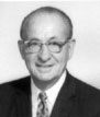
 NATHAN
SCHLESINGER: PRESIDENT, UTILITY ELEVATOR SERVICE, INC.
NATHAN
SCHLESINGER: PRESIDENT, UTILITY ELEVATOR SERVICE, INC. |
For some time, while working for Utility Elevator Company, I had it in the back of my mind to go into business for myself in the New York City area. Two fellow employees were interested in becoming partners — Harold Leon and Jack Abramowitz. Each put up $300 and I bought a lathe for $550 and the rest of the money for a drill press and a couple of motors for sanding. In 1926 we set up shop under the name G.A.L. Electro Mechanical service (G.A.L. being the initials of the partners). We started out making motor repairs and some elevator work, including recabling. Leon worked in the shop and took telephone calls, Abramowitz did motor repairs and I designed items and tried to sell them. An elevator interlock was one design I tried to peddle. It kept the elevator from running when the doors were open or unlocked. Another — a gate switch — was made at the rate of two dozen a week, Within six months we had a mimeographed catalogue with 10 items. Within two years we moved from the basement of a building on Amsterdam Avenue to larger space at 208 Centre Street, just off of Canal. Early in 1929 Jack left the company. He couldn't live on what we were making. I took home about $5 a week and we had several thousand dollars in receivables. Then on October 29 the stock market crashed. Customers couldn't pay us. They were broke and we were broke. We lived from hand to mouth but in 1931 we began to recoup. World War II was a difficult time for Germans living in the U.S. I was not eligible for the draft. We became part of the war effort, as did almost every machine shop and industry. At first we had second-rate contracts no one else wanted but later, because of our good work, we received larger and more complex contracts. We learned how to work with government specifications and ventured into new operations using new tools and material that served us well when the war ended. We were part of the "production miracle" — in 1942 the U.S. government was pumping $300 million a day into the economy and the jobless rate had gone from 8 million in 1940 to almost zero in 1945. During the war years the Gross National Product soared from 91 billion to $215 billion. Although the large corporations benefited the most some small companies were revived in those years/ G.A.L. was one of them! |
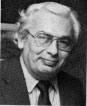
 HERBERT
PAUL GLASER
HERBERT
PAUL GLASER |
J.P.
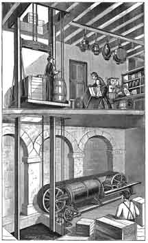
COPELAND: The Strutt's North Mill Hoist However, the West Reeling Mill, not the clock tower end, had a very old belt-driven hoist that had originally been driven off a line shaft that had been powered by a huge steam engine. This lift was Horce Glue from Farmer Green, and his wife used to be the cook for Chevin Cafe. The hoist, its size being about 6 ft-0 in. x 4 ft-6 in. at the load, passed for 1/2 ton (capacity) - again, a T&G wood cage on angle/channel iron frame. The drive was by electricity using flat leather belts three inches wide; the motor used a Vee belt reduction to the first drive shaft with two pullies 12" diameter by 7" face. Must have been two for two belts three inches wide to move over into drive. These belts drove onto a worm reduction shaft of the hoist wheel. This shaft carried fast and loose pullies for the crossed-up belt, giving a larger area round the pulley and an open drive down belt running in re- verse direction to the up belt - maybe four to five feet apart from the drive shaft. Belt striking forks (change over belt guides), moved the required up or down belt into drive mode, keeping the other belt on the free pulley. The driven pullies may have been a third larger in diameter to improve friction loss and area pulling power increased. The reduction worm crown wheel enclosed in oil bath, possibly Radicon or Crofts type, connected the output drive, the hoist head wheel and the lift cage by wire ropes, also the balance weight in the mill shaft. No speed governor, to my recollection, was fitted to this hoist in the event of a runaway or belt brake or slack belt not pulling the load. The other belt driving up or down hadto be eased over to stop me movement of the hoist Clue told me to always stand with my legs bent. I looked at him, noticing mat he was bow legged This put me off using the hoist for rides, taking to the stairs. The operator, on closing the outer door and inner gate, would start the lift by pulling a hemp rope. These two ropes went the full height of the mill round a wheel in the lift well and the other end to operate the belt-moving gear in the motor room. Pulling the up rope would move the drive belt onto the fixed dnve pulley. Note the two holes in the floor and the top of the hoist cage (accompanying graphic No. 1). The rope only moved when the man pulled it He never let his hands go free from the rope (which ran free until he gripped or pulled me opposite to travel direction) Moving off with a screech way up over head from the belt moving over to the drive pulley required a bit of skill on his part, I think. On arrival at the required floor level, he pulled the down-side rope, the belt forks putting the up-belt on the loose, free-running pulley. If one overshot the landing, he would ease the down side over just a touch - another screech and off you go. This hoist had call bells on each floor, but I have no knowledge of a bridge wheel on the drive in my recollection or floor level stops. This may have been when me old North Mill lift converted to electncity. The floor level door must have had a lock worked from me lift itself at each level. I question whether the inner gate had an interlock on closing to stop one pulling the control rope and monng the belt over to ~the drive. The cage was given a light globe when the drive was changed from steam to electricity. Young Jack Wolley inspected the works as a Saturday monning job. This hoist was taken out of service after the war, 1947-1948, and a new Evans lift was fitted in the clock tower end of the West Mill I do not remember any working lift or works in this shaft. We moved any heavy machine parts up the mill in this shaft by hanging up to three sets of hand chain blocks, working each in time (turn) to the required room floor. J. F. Copeland now helps out at the Bude Haven School workshops. He attends one-half day to help the technicians. The water wheel produced a horizontal rotation to an axle which engaged a vertical axle at the basement. The vertical axle was fitted with gears at the ceiling of each floor level. These engaged a horizontal axle at each floor which ran across the ceiling and provided power to the spinning wheels, looms and mill equipment. On the far end of the fifth floor, the horizontal axle was provided with pulleys arranged as shown in Figure 1 to drive the lift machine. The mill contains 15 arches in length. The floors are continued beyond the end wall by two additional arches, giving a small room on each floor which is occupied by the Counting House, the staircase, the stove which warms the mill in winter and also a crane (lift) for drawing the goods up to the machines on various floors. The Belper North Mill is one of the U.K.'s most important industrial buildings. Built in 1803-1804 on the site of an earlier cotton mill destroyed by fire, it represented, on completion, the pinnacle of engineering technology. The brick arch floors are supported on an iron frame and contribute to making the mill fire-proof. A warm air heating system was built in, as was a hoist between floors. The water wheel was very wide for the period, powering an extensive range of machines through a complex arrangement of belts and shafts. Sunday school was provided in the roof space.
|
|
It is important to remember that the inquiring mind was largely born in Italy. The earlier Greeks were adverse to experimentation, believing that they could determine the truth only with the power of the mind. This is why Galileo Galilei, the founder of the experimental method, is considered to be at a watershed in history. Galileo said, "No", to a dogmatic philosophy that had endured for 2000 years and ushered in an Age of Experimentation and Science, speaking out against the traditional church, teachers and institutions of the time. After Galileo was pressured to leave the University of Pisa for expounding his ideas he moved to the University of Papua and protection by the Venetian Republic's Doges, aristocrats who fostered freethinking. Latin, the language of the Romans, also played a part in the furtherance of experimentation. It was the language of the aristocracy, scholars and the elite; ideas could be expressed more clearly in Latin than in Greek. It was very important to translate and clarify contracts, pacts and other agreements and the first university degree given was in law — at the University of Bologna — the oldest in the world. A jurist had to know the exact meaning of each word and phrase. One could only be a Doctor in the Law after spending seven years in civilian law, six years for canonic law and five year for the liberal arts. Imagine emperors, kings and high church officials summoning Doctors of the Law for advice! Later the University of Bologna issued doctorates in Medicine, then in Philosophy. Its Law School was founded in 425 and the university, itself in 1088. The famed University of Prague, in the "Golden City" of Charles the Great, was founded more than 250 years later. The creation of the Vatican Library in the mid-1400 was also a great assistance to Italian scholars and researchers. As to Italian researchers and inventors we must recognize Luigi Galvanic, the discoverer of animal electricity, and Alexander Volta who discovered that electricity will be developed by two different metal discs — zinc and copper — in a solution of water and acid. Antonio Pacinotti in1860 invented the generator and Antonio Ferraris developed the rotating field AC motor, later mass-produced by Siemens, Edison and others. These were men of science, not industrialists and they sought few patents. There is no doubt but that the Industrial Revolution in England moved the development of the elevator ahead in geometric proportions but the inquiring minds of the great English inventors had a flowering centuries earlier on the Italian Peninsula. Written in 1979 by Umberto Sermedese, managing director of NORMA Company in Bologna, Italy |
 Umberto
Sermedese -- THE FOUNDATION OF ROMAN/ITALIAN FREE THINKING
Umberto
Sermedese -- THE FOUNDATION OF ROMAN/ITALIAN FREE THINKING|
The first idea for a gearless traction machine was patented by A.L. Dewelius on December 21, 1897. This scheme foresaw the trend at the end of the 20th Century by major manufacturers to use smaller but more numerous cables allowing a smaller drive sheave. With the light counterweight this equipment seemed more of a dumbwaiter or small goods lifts than a passenger elevator.
|
 JORIS
SCHROEDER: Birth of the Gearless
JORIS
SCHROEDER: Birth of the Gearless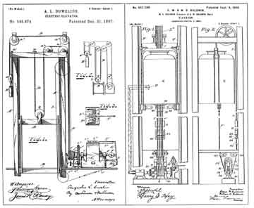
 On
the other hand the gearless elevator patented by C. W. and W.D.
Baldwin on September 4, 1900 was carefully thought out with an electric
reversing switch in the car and a governor geared to the drive shaft
at the lower level. This type of endless loop mechanism pre-dated
that used in the "Tower of Terror" at Florida's Disney World by
almost 100 year! The hoist cables endless loop in both schemes are
kept well tensioned by two tension screws in the pit and in both
an additional loop around a tension sheave assures minimum, or no,
slippage. The gearless equipment in the Disney attraction allows
the car to supposedly "free fall" for a maximum thrill but it is
always under full control during the drop, thanks to the tight grip
of the cables upon the sheaves. The Baldwin scheme introduced a
small diameter drive sheave along with multiple cables as well and
considering the small drive sheave diameter the cables must have
been of a small diameter.
On
the other hand the gearless elevator patented by C. W. and W.D.
Baldwin on September 4, 1900 was carefully thought out with an electric
reversing switch in the car and a governor geared to the drive shaft
at the lower level. This type of endless loop mechanism pre-dated
that used in the "Tower of Terror" at Florida's Disney World by
almost 100 year! The hoist cables endless loop in both schemes are
kept well tensioned by two tension screws in the pit and in both
an additional loop around a tension sheave assures minimum, or no,
slippage. The gearless equipment in the Disney attraction allows
the car to supposedly "free fall" for a maximum thrill but it is
always under full control during the drop, thanks to the tight grip
of the cables upon the sheaves. The Baldwin scheme introduced a
small diameter drive sheave along with multiple cables as well and
considering the small drive sheave diameter the cables must have
been of a small diameter. |
GEORGE JOHNSON Although the firm of George Johnson was founded in 1850 to do jobbing contracting it was not until 1864 that it began producing lifts. It is thought that Mr. Johnson developed the first builder's hoist. It was the subject of hostility by the bricklayers who thought the device would bring unemployment. Indeed, Mr. Johnson was subjected to several demonstrations when visiting job sites. The lathe and ripsaw in the shop were operated by foot treadle but a steam engine eased the manual operation of tools in 1870. Thirty-odd years latter a new gas engine was installed and when electricity came in the machines were driven by still another form of power. In the 1920's the firm rented lorries but 1950 saw the acquisition of a new t2o-ton Austin Lorry. His nephew, Mr. A.J. Littlechild in 1866, joined Mr. Johnson. The twelve-year-old boy was met at the train station and brought immediately to the firm to begin work. In time he took over management due to the ill health of Mr. Johnson. Mr. Frederick H. Brown, son-in-law of Mr. Little child, joined the firm in 1910 when the writer entered employment as a clerk. The war years threw a great strain on he partners as they strove to keep the business together. After the war they were joined by A. Donald Littlechild who had been in His Majesty's Forces for four years. The three men formed a limited company and the pent-up requirement for lifts caused the company to work at full capacity with deliveries running from one to two years. Many of our orders came fro the three of the main banks of England. Trolleys were developed to be used in conjunction with the lifts in the banks. In April 1941 the roof and front of the building was almost totally destroyed by a parachute bomb in the heaviest raid of the war. Only twenty of the company men were available to effect repairs, clearing away debris, repairing 3,000 square feet of roofing and a portion of the building front — a tremendous round-the-clock effort that allowed the firm to be back in business within 24 hours. It must be said that the founder was a man of considerable inventiveness. A model of one of his developments is on display at the National maritime museum in Greenwich. The scheme, accepted by the Royal navy in 1866 had to do with a type of steel casement upon which the gun would rotate. After firing the gun would turn and a part of the turret wall would close the porthole. This gave protection to the gunners when in a close firing situation with another ship. He was a skilled carpenter as well as an engineer and able to make an excellent model for inspection. Written by Will Brown of the Company in 1945 |
|
It was during his years at the University and the Polytechnic Institute in Berlin that the young man first became interested in the study of suspension bridges tutored by the celebrated Professors J. F. Dietleyn and J. A. Eytelwein. After receiving qualification as an engineer John A. Roebling and his younger brother, Karl, organized in 1831 a small group of the younger people and undertook to lead their emigration to the United States to the final adoption of a site near Pittsburgh for their proposed community. The town was at first called Germania, but later became known as Saxonburg.
At about this same time, there fell into Roebling's hands an obscure German engineering paper which described the experiments in Germany had been conducting in the matter of the fabrication of a rope out of wire and he began to experiment at his farm in Saxonburg in 1840. He approached the State Board of Public Works with the plan to substitute his wire rope for the hempen hawsers on the canal. There the reception accorded him was cool. But the rope worked. It lived up to every promise he had made for it; it was flexible; it was strong; it weighed no more than the huge hemp cables; its diameter of 1 1/4 inches made it considerably more convenient to work with; and it long outlasted the hemp. Three years later, in 1847, he built the wire rope suspension bridge across the Monongahela at Pittsburgh, and then, in 1850, he was engaged upon a project that was to startle the world. A suspension bridge across the gorge of the Niagara River, at Niagara. When it was finished,
and when Roebling dared to move a fully-loaded freight train across
it, the accomplishment was heralded by the press of the day as one
of the wonders of the world and the engineer was rocketed to fame. The successes attained by Roebling with his new wire rope, both as a haulage medium on the Pennsylvania Canal and as a suspension medium on bridges, made certain its wide acceptance as an industrial tool. Much of Roebling's time and energy were consumed in compiling data on the strengths of wire rope and in experimenting with new types of ropes to meet the demands of the many who sought to buy. In 1848, John A. Roebling purchased a three acre tract of land in Trenton, N. J., there to set up a wire rope factory being that it was near the Cooper Iron Works, his source of supply of wire.
Ferdinand and Charles formed an ideal combination; Ferdinand's interests centered upon the sales and financial aspects of the business. Charles, on the other hand, had an unusual genius for the development of products, of machinery, for the erection of plant buildings, and for the establishment of plant organization. Shortly after Morse invented the telegraph in 1844, telegraph wire was in great demand meeting the needs of this field and of the lightning rod field brought the Roeblings into their first contact with the manufacture of electrical wires as such. The principal insulation for the copper wire was a single or double cotton braid; consequently a minimum of simple machinery was required. It was not long, however, before the Roebling Company found it necessary to set up separate facilities for the production of electrical wires and cables. As the uses of electricity became more varied, so did the product which carried it. Insulations included: first cotton; then paper; then rubber; then silk and enamel and varnished cambric and all the many others. In the 1860's the Otis Brothers were experimenting in a field which since has become one of the largest consumers of wire rope. Until then, elevators had been used sparingly, and then mostly for industrial purposes because of their lack of safety mechanisms. The Otis Brothers, however, brought out safety devices which have been largely responsible for the expansion of the elevator industry. And the advent of wire rope, which John A. Roebling designed to suit their needs, contributed integrally to this development. |
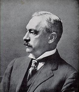
 THE
ROEBLINGS
THE
ROEBLINGS In
1837 he obtained employment as an engineer with the State of Pennsylvania,
and it was while working in this capacity that he first came in
contact with the Pennsylvania Canal construction project and was
presented with the situation which led to his fabricating America's
first wire rope. At various points along the route of the canal
it was necessary to transport the barges across the mountains by
means of portage railways. Large hempen hawsers were used to tow
the boats up the sides of the hills. These hawsers were nine inches
in diameter, and, obviously, cumbersome to handle, as well as expensive
because of the frequency with which they had to be replaced.
In
1837 he obtained employment as an engineer with the State of Pennsylvania,
and it was while working in this capacity that he first came in
contact with the Pennsylvania Canal construction project and was
presented with the situation which led to his fabricating America's
first wire rope. At various points along the route of the canal
it was necessary to transport the barges across the mountains by
means of portage railways. Large hempen hawsers were used to tow
the boats up the sides of the hills. These hawsers were nine inches
in diameter, and, obviously, cumbersome to handle, as well as expensive
because of the frequency with which they had to be replaced.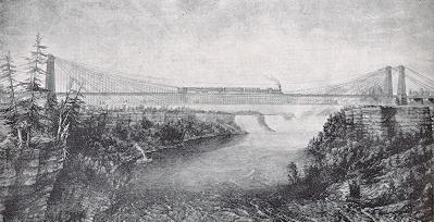
 During
the years that the Colonel was engaged in the building of the Brooklyn
Bridge, the John A. Roebling's Sons Company was assuming greater
and greater proportions as an industry, under the guidance of the
Colonel's two younger brothers, Ferdinand and Charles Gustavus.
During
the years that the Colonel was engaged in the building of the Brooklyn
Bridge, the John A. Roebling's Sons Company was assuming greater
and greater proportions as an industry, under the guidance of the
Colonel's two younger brothers, Ferdinand and Charles Gustavus.|
The ASME/ANSI A17.1 Safety Code Beginnings by William C. Crager The first edition of this Code was published in January 1921. It was prepared by an American Society of Mechanical Engineers (ASME) Committee on Pro: tection of Industrial Workers with the assistance of representatives of a number of interests including manufacturers, insurance carriers, regulatory bodies, and technical societies. The application of this Code in the formulation of various state and municipal codes emphasized the need for its further development and extension. Accordingly, ASME requested the American Engineering Standards Committee (AESC) to authorize the organization of a Sectional Committee to undertake this revision. They acted favorably on this request, and in January 1922, assigned sponsorship for the project jointly to the American Institute of Architects, the National Bureau of Standards, and ASME, all three of whom had taken an active part in the preparation of the first edition of the Code. The organization meeting of the Sectional Committee A17 was held in November 1922. A number of meetings of the Committee were held during the next two years and in July 1925, a revision of the 1921 Code was completed, approved by the AESC, and published as an American Standard. Subsequent to the publication of the 1925 revision of the Code, the necessity for development research on the design and construction of car safeties and oil buffers and for the development of test specifications for various parts of elevator equipment was realized. As a result, a Subcommittee on Research, Recommendations, and Interpretations was appointed in 1926. This subcommittee held regular meetings thereafter until interrupted by the war in 1940, and carried on an extensive test program at the National Bureau of Standards in connection with oil buffers and car safeties. Subsequent to the war, the name of this subcommittee was changed to ''Executive Committee for the Elevator Safety Code." The information gained as a result of these tests and the experience derived from the adoption and enforcement of the 1925 Code by various states and municipal enforcing bodies, together with the developments which had occurred in the design of the equipment as a result of installations made in very tall buildings, prompted the Sectional Committee to prepare and issue the third edition of the Code in 1931. The third edition was approved by the Sectional Committee in February 1931, and subsequently by the sponsors and by the American Standards Association (formerly the AESC) in July 1931. Further experience derived from the adoption and enforcement of the 1931 edition, and developments in the design of elevator equipment, led the Sectional Committee, in line with its policy of revising the Code periodically, to prepare the fourth edition in 1937, which was approved by the sponsors and by the American Standards Association (ASA) in July 1937. A fifth edition of the Code was well under way in 1940 when it was necessary to suspend the work due to the Second World War. However, a number of the revisions already agreed upon by the Sectional Committee and approved by the sponsors and by the ASA in April 1942, were issued as a supplement to the 1937 edition. They were subsequently incorporated in a reprint of the 1937 edition in 1945. In response to public demand, requirements for private residence elevators were also issued in a separate supplement, ASA A17.1.5-1953, and incorporated into the Code as Part V in the 1955 edition. The Sectional Committee reinitiated consideration of the fifth edition of the Code in 1946. Due to the considerable period which had elapsed since the fourth revision in 1937, and to the very extensive developments in the elevator art, the committee decided that the Code should be completely rewritten and brought up to date. Special subcommittees were appointed to prepare the revisions of the various requirements. The membership of each subcommittee consisted of persons especially familiar with the requirements to be covered by that subcommittee. Fifteen subcommittees were set up with a total membership of over 150 persons. The membership of these subcommittees was not confined to members of the Sectional Committee. It also included other persons having expert knowledge of the subjects under consideration by the subcommittees. These subcommittees and their personnel were listed in the 1955 edition of the Code. The drafts prepared by these subcommittees were widely circulated to interested groups for comment. After review of the comments and correlation of the drafts, the fifth edition of the Code was approved by the Sectional Committee, subsequently by the sponsors, and by the ASA in June 1955. William C. Crager served on various A17.1 code committees for 35 years. His career was dedicated to elevator safety as an engineer, consultant and author for over six decades. At the time of his death in 1987 he had been chairman of the A17.1 Committee for 15 years. |